|
Frequency and
Phase Angle
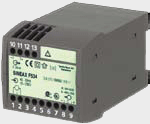
| SINEAX F534 |
|
| |

Manufacturer/Origin:
CamilleBauer/Switzerland
 |
Transducer for frequency
For the conversion of the frequency of a system into a proportional DC signal.
Customer benefit
• Determination of the progression and stability of the fundamental frequency of an electric system
• Standard as GL (Germanischer Lloyd), suitable for ships (only SINEAX design)
• Output signal useable for indication, registration, monitoring and control
• Safety by galvanic isolation and shock-proof terminals (IP20) |
Application
Frequency is an important command variable of electric systems or power distribution systems.
Variations of the system frequency particularly occur in system overload or underload situations. They
must be immediately recognised in order to take countermeasures in time. Frequency fluctuations
impair the performance of connected machines disproportionately. However, this can also be utilised
in drive engineering to improve start and speed characteristics e.g. in frequency converters where
the frequency is employed as a control variable.
The frequency is measured via a zero-phase voltage or voltage between phases which can be
directly connected via a converter. The instrument is also suited to distorted voltages with dominant
fundamental waves. A direct current signal proportional to the measured frequency is available at the
output.
Technical data
Meas. input: Input nominal voltage 10…230 V or 230…690 V
Meas. range: 45…50…55 Hz, 47…49…51 Hz, 47.5…50…52.5 Hz, 48…50…52 Hz,
58…60…62 Hz
or customised between 10 and 1500 Hz
Meas. output: Maximum output value 0…20 mA, 4…20 mA, 0…10 V or
customised in the 1…20 mA or 1…10 V range
Output signal unipolar, symmetrically bipolar or live-zero
Setting time selectable 2, 4, 8 or 16 cycles of the input frequency
Accuracy: Class 0.2 at 15…30 °C
Power supply: 24 – 60 V AC/DC or 85 – 230 V AC/DC (also internally from measurement input)
24 V AC / 24 – 60 V DC, connection on the low-voltage side
H x W x D: 69.1 x 70 x 112.5 mm (SINEAX),
assembly on top-hat rail (35 x 15 mm or 35 x 7.5 mm) |
| |
|
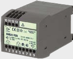
| SINEAX F535 |
|
| |

Manufacturer/Origin:
CamilleBauer/Switzerland
 |
Transducer for frequency difference
Acquisition of the frequency difference of two systems to be synchronised.
Customer benefit
• Determination of the frequency difference as a synchronisation control variable
• Standard as GL (Germanischer Lloyd), suitable for ships
• Output signal useable for indication, registration, monitoring and control
• Safety by galvanic isolation and shock-proof terminals (IP20)
|
Application
Voltage, phase and frequency balance are the basic preconditions to enable the parallel connection
of generators on one bus bar.
The frequency difference is determined by the simultaneous measurement of the voltages of the
bus bar and the generator unit to be energised. The instrument is also suited to distorted voltages
with dominant fundamental waves. A direct current signal proportional to the measured frequency
difference is available at the output.
Technical data
Meas. input: Input nominal voltage 10…230 V or 230…690 V
Meas. range: fS = 50 Hz: fG = 49.5…50…50.5 Hz, fG = 47.5…50…52.5 Hz,
fG = 47.5…50…52.5 Hz, fG = 40…50…60 Hz, fS = 60 Hz:
fG = 57.5…60…62.5 Hz or customised between 10 and 1500 Hz
[fS=frequency bus bar, fG=frequency generator]
Meas. output: Maximum output value 0…20 mA, 4…20 mA, 0…10 V or
customised in the 1…20 mA or 1…10 V
Output signal unipolar, symmetrically bipolar or live-zero
Setting time selectable 2, 4, 8 or 16 cycles of the input frequency
Accuracy: Class 0.2 at 15…30 °C
Power supply: 24 – 60 V AC/DC or 85 – 230 V AC/DC (also internally from measurement input)
24 V AC / 24 – 60 V DC, connection on the low-voltage side
H x W x D: 69.1 x 70 x 112.5 mm (SINEAX),
assembly on top-hat rail (35 x 15 mm or 35 x 7.5 mm)
|
| |
|
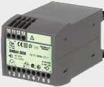
| SINEAX G536 |
|
| |

Manufacturer/Origin:
CamilleBauer/Switzerland
 |
Transducer for phase angle or power factor
Acquisition of the phase angle or power factor between the current and
voltage of a single-phase system or a symmetrically loaded three-phase system.
Customer benefit
• Monitoring of the reactive power requirement in energy distribution systems and process
engineering
• Determination of characteristic value for reactive power compensation
• Standard as GL (Germanischer Lloyd), suitable for ships
• Output signal useable for indication, registration, monitoring and control
• Safety by galvanic isolation and shock-proof terminals (IP20)
|
Application
The instrument serves the acquisition of losses which are caused by non-linear loads or reactive
impedances. During a day, these might strongly fluctuate which impedes static reactive power
compensation since overcompensation is not permitted.
The transducer for phase angle or power factor can be connected via current and voltage
transformer or directly. The instrument is also suited to distorted input variables with dominant
fundamental waves. At the output, a direct current signal proportional to the measured phase angle
or power factor between current and voltage is available.
Technical data
Meas. input: Single-phase alternating current system or 3/4-wire three-phase system of the same
load
Nominal voltage 100 V, 230 V, 400 V or customised 10…690 V
Nominal current 1 A, 5 A or customised 0.5…6 A
Nominal frequency 50/60 Hz or 10…400 Hz
Meas. range: Phase angle –60°…0°…+60°el or within –180°…0°…+180°el or
power factor 0.5…cap…0…ind…0.5 or
within –1…ind…0…cap…1…ind…0…cap…–1
Measuring span ≥20°el, unambiguous indication only up to –175°…0…+175°el
Meas. output: Maximum output value 0…20 mA, 4…20 mA, 0…10 V or
customised in the 1…20 mA or 1…10 V range
Output signal unipolar, symmetrically bipolar or live-zero
Setting time selectable 2, 4, 8 or 16 cycles of the input frequency
Accuracy: Class 0.5 at 15…30 °C
Power supply: 24 – 60 V AC/DC or 85 – 230 V AC/DC (also internally from measurement input)
24 V AC / 24 – 60 V DC, connection on the low-voltage side
H x W x D: 69.1 x 70 x 112.5 mm (SINEAX),
assembly on top-hat rail (35 x 15 mm or 35 x 7.5 mm)
|
| |
|
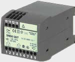
| SINEAX G537 |
|
| |

Manufacturer/Origin:
CamilleBauer/Switzerland
 |
Transducer for phase angle difference
Acquisition of the phase angle difference of two systems to be synchronised.
Customer benefit
• Determination of the phase angle difference as a synchronisation control variable
• Standard as GL (Germanischer Lloyd), suitable for ships
• Output signal useable for indication, registration, monitoring and control
• Safety by galvanic isolation and shock-proof terminals (IP20)
|
Application
Voltage, phase and frequency balance are the basic preconditions to enable the parallel connection
of generators on one bus bar.
The phase angle difference is determined by the simultaneous measurement of the voltage of the
bus bar and the generator unit to be energised. The instrument is also suited to distorted voltages
with dominant fundamental waves. A direct current signal proportional to the measured phase angle
difference is available at the output.
Technical data
Meas. input: Input nominal voltage 10…230 V or 230…690 V
Nominal frequency 50 Hz, 60 Hz or customised 10…400 Hz
Meas. range: –120°…0…120°el or customised within –180°…0…180°el,
in which measuring span ≥20°el, unambiguous indication only
up to –175°…0…+175°el
Meas. output: Maximum output value 0…20 mA, 4…20 mA, 0…10 V or
customised in the 1…20 mA or 1…10 V range
Output signal unipolar, symmetrically bipolar or live-zero
Setting time selectable 2, 4, 8 or 16 cycles of the input frequency
Accuracy: Class 0.2 at 15…30 °C
Power supply: 24 – 60 V AC/DC or 85 – 230 V AC/DC (also internally from measurement input)
24 V AC / 24 – 60 V DC, connection on the low-voltage side
H x W x D: 69.1 x 70 x 112.5 mm (SINEAX),
assembly on top-hat rail (35 x 15 mm or 35 x 7.5 mm)
|
| |
|
|